EL Testing of Solar Panels: How a Portable Electroluminescence Tester Works
EL testing of solar panels is the only practical way to see defects that a module cannot show you from the outside. A portable electroluminescence tester applies a forward-bias current to the module, the silicon cells emit near-infrared light in proportion to how well each area is working, and a camera captures that glow as an image. Cracks, dead cells, PID and broken gridlines appear as dark shapes against a bright, healthy background — typically within seconds per module, without dismantling the array.
This guide explains how the equipment works, how to read the images, and where portable EL testing earns its cost in real projects.
What EL Testing of Solar Panels Actually Reveals
Why cracks stay invisible to the eye
A micro-crack in a silicon cell is a fracture measured in micrometres. It does not break the glass, does not interrupt the module's output at standard test conditions by any obvious margin, and cannot be seen by looking at the panel or by wiping it clean. Thermographic cameras often miss it as well, because a crack only heats up once it starts carrying unbalanced current.
But a crack separates part of a cell from its busbar. That isolated area stops receiving current, stops emitting light, and therefore goes dark in an EL image. This is the core value: EL testing converts an invisible mechanical defect into a visible, documentable image.
What the camera captures
Crystalline silicon modules emit light in the 1,100–1,200 nm range when forward biased — outside the visible spectrum, which is why EL inspection is done in darkness with a near-infrared-sensitive camera. Brightness in the resulting image maps to minority-carrier lifetime and local current flow: bright means healthy and conducting, dark means restricted or disconnected, and unusually bright spots mean current is concentrating where it should not.
How a Portable Electroluminescence Tester Works
A portable EL tester packages a laboratory method into something one technician can carry up a ladder. Three subsystems do all the work.
Core components
The near-infrared camera
The camera uses a silicon sensor with the IR-cut filter removed, paired with a lens wide enough to frame a full module — typically 1.6–2.2 m diagonal — from a realistic working distance. Resolution matters more here than in ordinary photography, because a 1 mm crack on a 2 m module occupies very few pixels. High-resolution sensors (24 MP and above) are the difference between "there is something dark there" and "that is a finger break on cell row 4".
The current injection unit
EL imaging requires the module to be forward biased at a defined current, usually close to its short-circuit current, for a controlled exposure time.
String-level injection (up to 1,500 V)
The most efficient field method: the array is isolated, and the tester injects current into the whole string from a DC source or a dedicated power unit. One connection energizes dozens of modules in series, so a technician can image module after module simply by moving the camera. Units rated for 1,500 V DC systems are what modern utility-scale sites actually need.
Single-module bench injection
For loose modules, warranty inspections or lab work, the tester energizes one module at a time. This is the standard approach for incoming inspection and for any module that has already been removed from the structure.
Step-by-step field workflow
Step 1 — Isolate and prepare the array
Switch off the inverter, isolate the string, and confirm the safe working state with a meter. EL work is done with the current source under your control, never with the array live from the sun. Clear the module face and, in daylight, use a light-proof cover or hood — sunlight floods an IR camera far more effectively than any filter can compensate for.
Step 2 — Energize the module under test
Connect the injection leads to the string or module terminals, set the current to the value specified for that module type, and let the cells stabilize. Stabilization time matters: a module that was just in full sun holds thermal gradients that distort brightness, so allow it to cool and settle before judging uniformity.
Step 3 — Capture and repeat
Fire the exposure, check the histogram, and reframe if the module is clipped. A well-run inspection produces one clean, labelled image per module, tied to its serial number and string position — that record is the whole point, because a crack without a timestamp and a location is not evidence of anything.
Reading an EL Image: Defect Types and What They Mean
Cracks and cell damage
Micro-cracks
Micro-cracks appear as thin dark lines, often branching, usually originating at cell edges or near solder points. A single hairline crack may be electrically harmless today and become a hot-spot risk or a PID pathway after years of thermal cycling. Documenting its position and extent at installation is how you win a damage claim later.
Broken gridlines and fingers
When a finger is interrupted, the current path in that cell narrows. In EL the cell appears uniformly dimmer, or shows a darker stripe running in the direction of the finger. Broken busbars show up as wider dark bands. These are the defects that quietly cost yield across an entire array.
Potential-induced degradation (PID)
PID appears as darkening that begins at the cell edges nearest the frame and spreads inward, or as whole cells losing brightness in a pattern that follows the module's voltage gradient. It is an electrical and chemical failure driven by high system voltage, humidity and temperature — not mechanical damage. EL is the fastest way to distinguish PID from cracking, because the two have completely different signatures and completely different remedies.
Inactive cells, shunts and solder failures
Dead cells
A completely dark cell in an otherwise bright module is either electrically disconnected or physically destroyed. Cross-check against the IV curve: a dead cell usually produces a step or a shoulder in the curve.
Shunt defects
A shunt is a low-resistance path that leaks current across the junction instead of pushing it out of the module.
How shunts show up in EL
Under forward bias, a shunted region glows brighter than its neighbours — current is flowing, but not doing useful work. That inverted signature is why shunts are frequently misread: bright is not always healthy in EL. Compare against neighbouring cells at the same exposure before drawing conclusions.
Where Portable EL Testing Pays Off: Real Use Cases
This is where the equipment stops being a lab curiosity and starts protecting money.
Incoming inspection before installation
Modules travel by truck, ship and crane before they ever generate a kilowatt-hour. Transport damage is common and warranty windows are short. Imaging a sample — or the full batch on high-value projects — at the warehouse establishes a baseline that no supplier can dispute later.
Commissioning and construction quality control
On an EPC project, EL images taken before and after installation separate manufacturing defects from handling damage. If a crack is present at handover and absent at delivery, the responsibility is clear. Many owners now require EL documentation as a commissioning deliverable, alongside IV curve tracing and insulation resistance tests.
Post-event diagnosis after hail, storm or impact
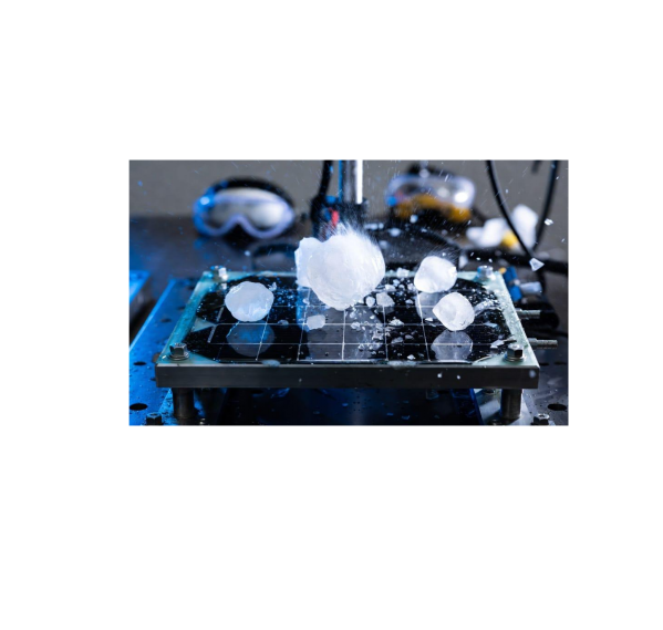
After a hail event, the visible question is glass; the expensive question is cell-level damage beneath intact glass. A portable tester turns a day of climbing and guesswork into a set of images that tell you exactly which modules need replacement and which are unaffected.
Second-hand purchases and warranty claims
Buying a used array without EL images is buying blind. For warranty claims, the image is the argument: a supplier who sees a documented finger break with a timestamp rarely argues about the physics.
Manufacturing and R&D quality control
Even where a full EL cabinet exists on the line, a portable unit is what engineers use for root-cause analysis — pulling a failed module, imaging it immediately, and comparing it against the process change under test.
O&M and underperformance investigation
When a string underperforms and the IV curve is ambiguous, EL answers the question the thermal camera cannot: is this a connection problem, a cell problem, or a module that was damaged before it was ever installed?
EL vs thermal imaging vs IV curve tracing
|
Method |
What it detects best |
What it misses |
|
EL imaging |
Cracks, PID, dead cells, broken fingers, shunts |
Faults that only appear under real irradiance and load |
|
Thermal (IR) imaging |
Hot spots, bypass diode failures, string mismatches |
Mechanical cracks that are not yet heating |
|
IV curve tracing |
Power loss, mismatch, series/shunt resistance |
Where inside the module the loss originates |
The three are complementary. EL tells you what is wrong inside the cell; thermal tells you what is getting hot; IV tells you what it costs you.
Choosing a Portable EL Tester: What Actually Matters
Resolution, lens and working distance
Ask for the pixel count and the field of view at your real working distance, not the marketing megapixels. A camera that frames a full module from 3 m with 40 MP resolves defects that a 12 MP unit at 1 m cannot. For strings, confirm the unit handles 1,500 V systems and offers string-level injection, or you will be reconnecting leads all day.
Power, weight and dark-environment practicality
Field EL happens at night, on roofs, in winter. Battery runtime, total kit weight and setup time decide whether the tool gets used or stays in the van. A hood or shroud integrated into the camera head is worth more in practice than another 4 MP of sensor.
Software and reporting
The image is only evidence if it can be filed, labelled and exported. Look for serial-number tagging, string/location metadata, batch export and a PDF report format your client or insurer will accept. Reference the international practice in IEC 60904 for EL imaging of PV modules when specifying the test method — it gives both sides of a contract a shared definition of a valid image.
Frequently Asked Questions
Can EL testing be done in daylight?
Not directly. Sunlight overwhelms the near-infrared signal, so field EL work is done at night or with a light-proof cover. Benchtop testing in a dark room is the standard alternative.
Does EL testing damage the module?
No. The module is forward biased at roughly its operating current for a few seconds — a normal electrical condition. The method is non-destructive and does not require disassembly.
How long does a field inspection take?
Per module, capture is a matter of seconds; total time is dominated by access, isolation and moving between rows. String-level injection is what makes array-scale inspection practical, because the electrical setup happens once.
Can EL testing detect PID before power loss is visible?
Yes — PID shows as edge darkening in EL before the IV curve shows a meaningful drop. That early warning is one of the strongest arguments for including EL in routine O&M.
Conclusion
EL testing of solar panels answers a question no other field method answers cleanly: what is happening inside the cell? A portable electroluminescence tester puts that answer within reach of a single technician — at the warehouse, on the roof, after the storm, and in the middle of a warranty dispute. Cracks, PID, dead cells and shunts stop being theories and become images with serial numbers and timestamps.
If your projects involve high-value modules, tight warranty windows or utility-scale strings, EL inspection is not an optional extra. It is the cheapest insurance you will buy on the array.
Testing modules for the first time, or specifying EL inspection for a project? Share your module type, string voltage and site conditions, and we will help you match the right portable EL configuration to the job.
PV Module Mechanical Load Testing Machine: Testing Solar Panel Strength and Reliability
Related Article